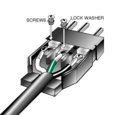
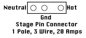
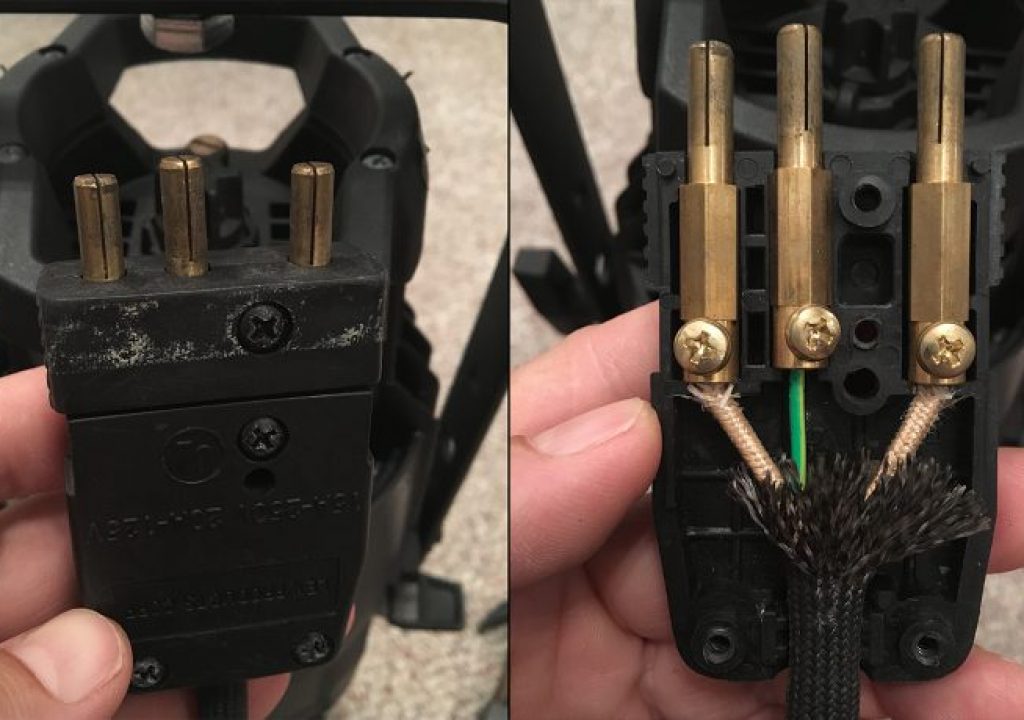
stage pin connector wiring diagram
To keep the system simple as it is we will go step by step to show how to install a CCTV Closed Circuit Television security camera in home office and other sensitive places where it needed to monitor and control the security and manage proper system for better protection. The relay system bypasses the stock headlight wiring which isnt heavy duty enough to handle the increased wattage of the new bulbs.
Electrical Connectors
IP Camera Installation Wiring Diagram with NVR System.
. Your woofer may use one of the following to identify - terminals. 6-Pin Wire Harness Assembly Installation Guide Alternator Specs In addition to wiring diagrams these guides also provide information on Alternator Identification and procedures for an engine replacement with a new Briggs Stratton engine that utilizes a. The 3-stage thermal lock extrusion with dual fan forced induction keeps everything cool while real-time thermalprotection schemes safeguard the amplifier.
There are two versions. Hello nice to meet you I got problem with my R300 BT Radio and need R300 BT wiring diagram for opel astra K 2017 sport tourer to repair it can you plaeas send the diagram or pins info from R300 BT wiring diagram opel. Connector Pin-out Diagram The 12 terminal socket shown above is used on nearly all GM radiosstereostape players from 1978 up into the early 1990s certain models.
Perfect for hybrid electric. A wiring diagram typically provides. Ignition system component part numbers.
When the input voltage drops to between 45 V and 68 V the NI roboRIO enters brownout mode with a staged response as Table 2 describes. In the initial stage you can use the monitor to check the live recording of camera if they are working properly. They is a 6 pin plug with red black and brown on bike and an 6 pin plug with red black green blackwhite on ignition switch all of them in completely different positions.
Im looking the complete engine wiring diagram schematic thats color coded for my 4dr 1994 honda civic sedan has a. In our case the power supply is built-in in the NVR system. P1 is a 5 pins XH connector that is used to apply the chips supply and control signals to the board.
Monitors the voltage on the input voltage pin. KB614 BDL168 PM42 SE8C Recommended Wiring Procedure For 44 Pin Connector. The image below is for quick reference but I recommending downloading the PDFs file below for much more detail and the ability to printzoom in.
The XLR connector is a type of electrical connector primarily found on professional audio video and stage lighting equipment. Upgrading to 80-100 watt bulbs definitely requires the use of relays. A switch of this type was fitted to MGB and TR6.
Hi does anyone have a wiring diagram for lexmoto assault efi 2019 the ignition switch they sell on cmpo doesnt fit to wiring loom on bike. Please add 2006 alto ecu pin out and wiring diagram with pdf 355. The circuit is simple inexpensive and can be made small enough to fit inside an XLR backshell or mounted onto a euro-block connector.
It shows the components of the circuit as streamlined shapes and also the power as well as signal connections between the gadgets. Designation in Wiring Diagram. High Wattage Headlights Wiring Diagram.
A wiring diagram is a simplified conventional photographic representation of an electric circuit. 4-Pin harness Rear HighLow Level. They are most commonly associated with balanced audio interconnection including AES3 digital audio but are also used for lighting control low-voltage power supplies and other.
The problem may be a malfunction of the regulator or poor contact with the wiring as well as a clogged connector or the formation of rust on its pins. See Whats Inside the New Sonnax 4L80-E Performance Pack. However using three-pin XLR connectors for DMX512 is specifically prohibited by section 712 of the DMX512 standard.
Stage Series LED lighting has been extensively tested for long-term operation from -40 to 185 degrees F along with vibration moisture intrusion and corrosion testing. Features multi-impedance Constant Power inputoutput clip detection top mounted controls and dual fan forced induction cooling. For detailed instructions about connecting to the vehicles power door lock systems refer to the Door Lock Wiring guide Document No.
Connecting wires securely to this connector requires soldering skills. It should be noted that the wiring diagram shown here is physically correct for the switch but the terminals on the base are marked incorrectly. CCTV Camera Installation Wiring with DVR Security System Step by Step.
Guess what bike doesnt. Terminal 1 on the switch corresponds to Terminal 3 on the diagram and visa versa. 1041 available to authorized dealers only from the technical resources listed at the front of this guide.
So you can directly connect the NVR by three pin plug using 120V AC or 230V AC depends on your region. P17 16-pin diagnostic connector R14 glow plug R15 glow plug R16 glow plug R17 glow plug R39 1 heating element of the ventilation duct S40 3 clutch pedal switch W4 mass shield point of the engine W5 mass point of the seat box W7 engine compartment mass point X26 38 electrical plug connection of the engine wiring harness. The connectors are circular in design and have between three and seven pins.
1996-2000 Chevrolet Tahoe 4x2 and 4x4. The socket is divided into three 4 terminal sections power front speakers and rear speakers. Here is a wiring diagram showing three resistors providing this passive mixer circuit.
Door Lock Harness H2 3-PIN Connector ___ ___ ___ NOTE. Figure 3 shows the PCB layout of. Sonnax Transmission parts for GM 4L80-E applications.
NI roboRIO Input Voltage Brownout Behavior Stage Input Voltage Range Behavior 1 63 V to 68 V The 6 V voltage rail starts to drop. The illustrations in the diagnostic manual are printer friendly. Complete step-by-step testing instructions.
1996-2000 GMC Yukon 4x2 and 4x4. Ez Go Golf Cart Wiring Diagram Gas Engine. One shows a 60 amp Renogy DC-DC charger which requires an ignition trigger wire details in this section of the post and is one single deviceThe other diagram shows 2x.
The use of any other XLR style connector is prohibited. This diagram is fo using high-wattage bulbs with stock headlights. K1 is a KF45 power connector that is used to connect the motor and motors supply wires to the board.
The three-pin XLR connector is commonly used for DMX512 on lighting and related control equipment particularly at the budgetDJ end of the market. Our Heavy Duty Dual Output 4-Pin Harness can be used to power up to four Stage Series 2 pods. Supplied complete with key and barrel.
The Power T400X4ad is an ultra-compact high efficiency 400 Watt 4-channel amplifier. Collection of ez go golf cart wiring diagram gas engine. Do you have a recommend wiring procedure for the 44-pin edge connector on the PM42 and SE8CPM42 PM4 BDL168 BDL16 BDL162 SE8C use a 44-pin edge connector.
-Ignition coil 1 with power output stage -N70-Ignition coil 2 with power output stage. Peripheral Plug-In Harnesses Super Bright. Parallel parking assistance control module -J791- 16-pin connector -T16- diagnostic connector Automatic dimming interior rearview mirror -Y7 - Left washer nozzle heater -Z20- Right washer nozzle heater -Z21-.

Rosco 20a Male Stage Pin Plug Connector Inline Barndoor Lighting
Electrical Connectors

Stage Lighting For Students
How To Rewire A Bates Power Cord By Matthew Jeppsen Dp Notes Provideo Coalition